 By Jocelyn Ian
Every physical product starts as an idea, yet the distance between a rough sketch and a reliable manufactured part is often measured in costly missteps. A bracket that interferes with a neighboring housing during final assembly, a casting wall too thin to fill cleanly, or a tolerance stack-up that only surfaces after five hundred units are machined can derail a production schedule fast. On modern factory floors, computer-aided design serves as the digital foundation that catches those problems before metal is cut or molds are hardened.
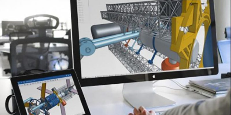
Far more than a faster way to draft two-dimensional blueprints, modern CAD platforms build rich three-dimensional models packed with geometric precision, material properties, and assembly relationships. By connecting design geometry directly to downstream engineering, tooling, and shop-floor execution, computer-aided design turns manufacturing from a trial-and-error craft into a repeatable, data-driven discipline.
Catching Design Flaws Before Tooling Begins
Building physical prototypes for every design tweak is slow and expensive, especially when custom injection molds, stamping dies, or investment casting patterns are involved. Soft tooling alone can take weeks and tens of thousands of dollars, while hard production tooling demands far greater commitment. Catching an error on a digital screen costs a fraction of fixing it on a press or milling bed.
In a parametric 3D model, engineers can check clearances across full range-of-motion assemblies, verify fastener access, and spot awkward undercuts or sharp internal corners that concentrate stress. When a mounting boss sits two millimeters too close to a cooling channel or a sheet-metal bend radius is too tight for the alloy, adjustments happen in minutes rather than weeks.
Simulation and Design for Manufacturability
Many modern CAD environments integrate directly with finite element analysis, thermal and fluid modeling, and design for manufacturability checks. Instead of guessing how a housing will deflect under load or how molten polymer will flow through a complex cavity, engineers can test virtual scenarios under realistic constraints.
Design for manufacturability rules flag features that complicate machining setups, require exotic tooling, or create unnecessary scrap. Simplifying a pocket radius so a standard end mill can reach it or adjusting draft angles on a molded part reduces cycle times and improves first-pass yield long before production ramps up.
Seamless Hand-Off to CAM, Tooling, and Production
A clean CAD model pays its biggest dividends when it moves smoothly into the next stages of manufacturing. Computer-aided manufacturing software reads 3D geometry directly to generate toolpaths for CNC mills, lathes, routers, and multi-axis machining centers, while additive manufacturing slicers convert solid models into layer-by-layer build instructions.
Because the geometry is already defined digitally, shop-floor programmers spend less time re-measuring drawings and less time interpreting ambiguous callouts. Fixtures, jigs, and inspection programs can also be built around the exact same master model. When design, tooling, and quality inspection share a single digital source of truth, fewer translation errors slip through between engineering and the shop floor.
That alignment also shortens new product introduction cycles. While tooling engineers design fixtures and machinists prepare toolpaths on one track, supply chain teams can review part geometry for sourcing and cost estimates on another. Parallel work compresses lead times without sacrificing precision.
Managing Revisions Across Teams and Suppliers
Modern manufacturing rarely happens inside a single building. An industrial equipment maker in the Midwest might partner with a contract fabricator in another state, a specialized electronics enclosure vendor overseas, and an internal quality lab testing compliance. Without strict version control, out-of-date drawings and conflicting file formats quickly cause chaos.
Modern CAD workflows—especially when paired with product data management or cloud-based collaboration tools—keep revision histories clear and accessible. Engineers can track who changed a hole diameter, why a wall thickness was updated, and whether a revision affects mating parts in a larger assembly. Native and neutral file exchanges make it easier to share geometry with suppliers while protecting proprietary intellectual property through controlled permissions.
Reducing Scrap, Rework, and Material Waste
Scrap and rework eat quietly into manufacturing margins. Every scrapped casting or mis-drilled manifold wastes raw material, machine spindle hours, energy, and labor. Better upfront geometry verification and tighter dimensional control directly reduce those losses.
CAD also supports lightweighting and generative design, where software explores structural load paths and removes excess material from areas carrying minimal stress. Trimming unnecessary mass from an aerospace bracket, an automotive suspension component, or a conveyor frame lowers raw material consumption per unit and can reduce shipping weights across the entire supply chain. Even when parts are produced via subtractive machining, accurate stock models help optimize nesting and roughing passes to leave less waste behind.
Practical Limits and What CAD Cannot Do Alone
As capable as CAD has become, treating it as a cure-all creates its own hazards. A model that looks flawless on a high-resolution monitor can still fail in real-world service if underlying assumptions are wrong. Overly optimistic boundary conditions in a simulation, unverified material datasheets, or ignored surface-finish requirements can produce a clean CAD file that performs poorly on the machine.
Shop-floor realities still require hands-on judgment. Machinist experience with chatter, fixture deflection, coolant flow, and chip evacuation remains essential when turning digital toolpaths into real parts. Similarly, close communication between design engineers and production operators prevents ivory-tower designs that are mathematically valid yet awkward to assemble or inspect under everyday factory conditions.
Making Digital Precision Work on the Shop Floor
Computer-aided design delivers lasting value when companies treat it as an integrated workflow rather than an isolated drafting station. Clear modeling standards, consistent tolerances, tight version control, and regular feedback loops between engineers and floor technicians turn digital models into dependable hardware. Manufacturers that get those fundamentals right move from concept to stable production faster, waste fewer materials along the way, and build products that hold up under real operating demands.
What is your reaction?
Excited
0
Happy
0
In Love
0
Not Sure
0
Silly
0